What are the causes and troubleshooting steps for LCD screen power failure?

Power failures in liquid crystal displays (LCDs) can generally be categorized into two main parts: external power adapter and supply, and internal motherboard power circuit
Power failures in LCD screens can generally be divided into two main parts: external power adapter and supply, and internal motherboard power circuit. The figure below clearly illustrates the core composition of the power system and the logic for troubleshooting:
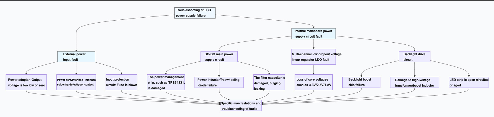
Below are the specific manifestations, causes, and troubleshooting approaches for various types of malfunctions:
fault category | Specific fault point | Common phenomena and possible causes | Key troubleshooting methods |
External power supply and input | 1. Power adapter | No voltage output, or voltage significantly below the nominal value (such as 12V). This results in the screen not being powered up at all. | Replacement method test: Replace the adapter with one that has the same voltage and a current equal to or greater than the original specification. |
2. Power cord and interface | The interface is loose, the internal wire core is broken, and the DC socket is poorly soldered. When the cable is shaken, the screen flickers on and off. | Check the interface, measure the voltage of the mainboard terminal interface with a multimeter, and shake the cable to see if the voltage changes. | |
3. Input protection circuit | The fuse is blown, usually due to a short circuit in the subsequent stage or an instantaneous overcurrent. | Conduct a visual inspection or use a multimeter to measure continuity. Before replacing the fuse, it is necessary to troubleshoot for any short circuits. | |
Internal mainboard power supply circuit | 4. DC-DC main circuit (Core) | The power management chip is damaged, such as TPS54331, MP2307, etc. There is no output or severe heating. | Measure the chip's input voltage (VIN), enable signal (EN), feedback voltage (FB), and output voltage. |
The open circuit or magnetic saturation of the power inductor leads to no output or poor load capacity. | Measure the inductance resistance (which should be close to 0Ω), or observe whether it changes color or has a burnt smell. | ||
Damage to the filter capacitor, such as bulging or leakage, can lead to excessive power ripple, system instability, or a black screen. | Conduct a visual inspection, or measure the capacitance value with a capacitance meter (soldering is required). | ||
5. LDO voltage regulator (Multi-channel voltage) | The LDO providing voltages such as 3.3V, 2.5V, and 1.8V for MCU, memory, etc. has failed, resulting in the core board not working. | Measure the output voltage of each LDO in turn, compare it with the specification, and check whether the input is normal. | |
6. Backlight drive circuit (Independent system) | The backlight boost chip is non-functional or damaged. The screen displays a faint image but lacks backlight (visible only under strong light). | Measure the chip power supply, enable signal, and boosted high-voltage output (be careful! It can reach tens of volts). | |
The boost inductor/transformer is damaged, or the LED strip is open-circuited, or the LED beads are aging. | To test the continuity of the inductance, or use an LED tester to individually test whether the light bar is illuminated. |
Supplementary suggestions and precautions
1. Safety first: When disassembling for inspection, be sure to disconnect all power sources. The large capacitors on the motherboard (especially in the backlight circuit) may store high voltage, so do not touch them directly with your hands.
2. Follow the procedure: It is recommended to troubleshoot in the order of "from the outside to the inside, from simple to complex", that is, first confirm that the external power supply is normal, and then check the internal circuit.
3. Make good use of your senses: listen for any unusual noises, smell for any burnt or charred smells, observe for any obvious discoloration, bulging, or ablation of components, and (carefully) feel for any abnormal heat on the chip.
4. Professional support: For complex malfunctions involving multi-layer PCBs, BGA packaged chips, or requiring program programming, it is recommended to seek professional repair or contact the original manufacturer.
I hope this detailed checklist can assist you in pinpointing the issue. If you require further guidance on how to use a multimeter to specifically measure the voltage at a critical point, or on the typical operational circuit of a specific chip, I am prepared to provide additional clarification.
TFT LCD:https://www.idtdisplay.com/
AUO LCD Display:https://www.idtdisplay.com/products/AUO_LCD_Displays/