How to determine whether the LCD is driver board fault or logic board fault?

Distinguishing between a driver board (Main Board) and a logic board (TCON - Timing Controller) fault is a critical skill in industrial LCD repair The core principle is to follow the signal path and isolate the faulty component
How to determine whether the industrial LCD screen is a driver board fault or a logic board fault?
Distinguishing between a driver board (Main Board) and a logic board (TCON - Timing Controller) fault is a critical skill in industrial LCD repair. The core principle is to follow the signal path and isolate the faulty component.
Here is a structured, step-by-step guide to accurately diagnose the problem.
Core Concept: The Signal Path
1.Driver Board (Main Board): The "computer." It receives video input (e.g., HDMI, VGA, DVI), processes it, and outputs a standardized LVDS (Low-Voltage Differential Signaling) or V-by-One signal to the logic board.
2.Logic Board (TCON Board): The "translator." It receives the LVDS signal from the driver board, converts it into precise timing signals (ROW and COLUMN commands), and sends them to the actual LCD glass panel to control each pixel.
A fault in either board will prevent a correct image from being displayed.
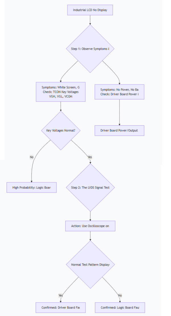
The following diagnostic flowchart provides a visual guide for the troubleshooting process:
Step-by-Step Diagnosis Methods
Method 1: Symptom Observation (Preliminary Clues)
Typical Logic Board (TCON) Failure Symptoms:
White Screen: Backlight is on, but the screen is completely white. (Most common indicator).
Gray Screen: Backlight is on, screen is gray with no content.
Vertical Lines/Bars: Solid or multi-colored vertical lines that span the entire height of the screen.
Negative Image: The image appears as a color-inverted photo negative.
Typical Driver Board Failure Symptoms:
"No Signal" Message: The screen can display its own on-screen display (OSD) but shows "No Signal" when the source is connected. This strongly suggests the driver board is not processing the input signal.
Artifacting/Glitches: Corrupted images, blockiness (pixelation), or frozen screens, while the backlight remains on.
Complete Black Screen (No Backlight): This could be a driver board issue (no power-on signal sent) or a separate backlight/inverter problem. Use a flashlight and look very carefully at the screen for a very faint image to rule out backlight failure.
Method 2: Voltage Measurement (The Most Practical Method)
This requires a multimeter and is the most effective way to isolate the problem on the logic board.
Locate the Logic Board (TCON): It's a small, separate PCB usually located at the top or bottom of the LCD panel, connected to the driver board by a single or dual LVDS cable(s).
Identify and Measure Key Test Points: On the logic board, look for labeled test points (often marked with silkscreen text). Critical points to check include:
Fuse (F1): Measures input voltage (e.g., 12V, 5V, 3.3V). If this is 0V, the logic board has no power.
VCC: The main logic voltage (often 3.3V or 5V).
VGH (Vgate High): The voltage to turn ON the TFT transistors. Typically +15V to +30V.
VGL (Vgate Low): The voltage to turn OFF the TFT transistors. Typically -5V to -15V.
VCOM: A critical reference voltage for the liquid crystals.
Interpret the Results:
If VGH or VGL is missing or significantly out of range, the logic board is definitely faulty. This is the most common cause of a white screen.
If all key voltages on the logic board are present and correct, the fault most likely lies with the driver board or the LVDS cable.
Method 3: The "Board Swapping" Test (The Most Definitive Method)
This involves using known-good components to isolate the fault.
The LVDS Signal Test (TCON Tester):
Action: Disconnect the LVDS cable from the main driver board. Use a dedicated LCD TCON Test Board (a "screen tester"). This device generates universal test patterns (color bars, grids) and connects directly to your logic board's LVDS interface.
Result:
If the screen displays the test pattern perfectly: Your logic board and LCD panel are good. The fault is 100% in the driver board.
If the screen still shows a white screen or other abnormality: Your logic board (or the LCD panel itself) is faulty.
Physical Board Replacement:
Replace the Driver Board: Swap in a known-good, compatible driver board. If the display works, the original driver board was faulty.
Replace the Logic Board: Swap in a known-good, compatible logic board. If the display works, the original logic board was faulty.
Method 4: Waveform Analysis (For Advanced Users)
Tool: Oscilloscope.
Action: Probe the LVDS connector pins on the driver board (with the cable connected and the system powered on).
Result:
If you see complex, changing waveforms on the data pairs and a steady clock signal, the driver board is likely outputting a signal, pointing towards the logic board.
If there is no activity or the waveform is flat/static, the driver board is suspect.
Summary and Quick Reference
Method | Driver Board Fault Indicator | Logic Board (TCON) Fault Indicator |
Symptoms | "No Signal" message; artifacts; powers on but no image. | White screen; gray screen; vertical lines; negative image. |
Voltage Check | Output voltage to TCON is normal. | Key TCON voltages (VGH/VGL) are missing or abnormal; fuse is blown. |
TCON Tester | Screen displays test pattern correctly. | Screen remains white/abnormal with tester. |
Board Swap | Replacing driver board fixes the issue. | Replacing logic board fixes the issue. |
Final Recommendation:
Start with symptom observation, then proceed to the voltage measurement on the logic board. If you lack the tools or confidence, using a TCON tester is the most straightforward and conclusive way to determine which board has failed. Always remember to handle boards and connectors with care to prevent electrostatic discharge (ESD) damage.