LCD screen lighting steps and common troubleshooting

To light up the LCD screen, it is necessary to prepare a hardware preparation list, lighting operation steps,
To light up the LCD screen, it is necessary to prepare a hardware preparation list, lighting operation steps, and key precautions.
To light up the LCD screen (taking the Tianma 8-inch P0840SVN1MB00 industrial screen as an example), systematic operation is required. The following are the key steps and precautions:
I. Hardware Preparation Checklist
Category | Required components | Function Description |
Core Drivers | 1. LCD screen driver board (including LVDS decoder) | Convert the signal source into LVDS signal recognizable by the screen line |
2. Power adapter (5V/12V) | Match the input voltage of the screen (refer to the specification sheet) | |
Connect Assembly | 3. LVDS screen cable (dual channel/single channel) | Ensure interface matching (e.g. 30pin/40pin) |
4. Backlight inverter or LED driver board | Provide constant current/constant voltage power supply for backlight strips | |
| Signal source | 5. Main control board (ARM/FPGA, etc.) | Output RGB/LVDS signals and control timing |
Auxiliary tools | 6.Multimeter/Oscilloscope | Check if the voltage and signal waveform are normal |
7. Electrostatic wristband | Prevent ESD from penetrating the LCD module |
II. Lighting operation steps
1. Circuit connection
Power layer: driver board power input → screen power pin (strictly check the polarity of VCC/GND)
Signal layer: Main control board LVDS output → Driver board input → LVDS screen cable → LCD screen interface
Backlight layer: The inverter input is connected to the driver board, and the output is connected to the screen backlight strip (note the high voltage risk!)
2. Parameter configuration
Set voltage/current according to the specifications:
Main power supply: 5V ± 0.25V (typical value, subject to specifications)
Backlight current: calculated based on the number of LED strings (e.g. 6 LED strings ≈ 120mA)
O Timing matching:
Configure resolution (800 × 600), refresh rate (60Hz), and LVDS channel count in the driver board firmware
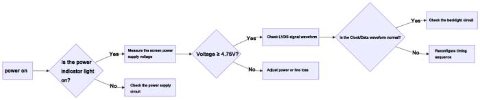
3. Power on detection
III.Key precautions
1. Electrostatic protection (ESD)
Wear an anti-static wristband throughout the operation, and lay anti-static mats on the workbench
Before touching the touch screen cable, touch the grounded metal to release static electricity
2. Interface foolproof design
The LVDS screen cable socket has a foolproof buckle that prohibits forced insertion
Confirm the direction of the screen line (such as the PIN1 marking point on the screen)
3. Backlight safety
LED backlight driver requires current limiting protection to avoid overcurrent burning of light beads
CCFL backlight inverter outputs high voltage of 300-800V, and touching with live electricity is strictly prohibited
4. Signal compatibility
LVDS differential impedance needs to be matched with 100 Ω± 10% (with parallel resistance added between differential pairs)
Clock signal jitter (Jitter) ≤ 0.3UI (unit interval)
5. Environment debugging
Gradually increase the backlight brightness when first lit up and observe for any local dark spots
Monitor the screen temperature in high temperature environments (>60 ℃) to avoid LCD failure caused by overheating
IV. Common troubleshooting
Phenomenon | Possible reasons | Solution |
White screen (no image) | Backlight is normal but there is no signal | 1. Check the LVDS connection2. Test is the main control output enable signal |
Flower screen/stripe | Timing mismatch or EMI interference | 1. Reconfigure the timing parameters of the driver board2. Screen cable with magnetic ring |
Local dark area | Backlight LED damage or light bar virtual soldering | Use a multimeter to detect LED string failure and replacefaulty LED beads |
Screen flicker | Insufficient power supply or backlight PWM conflict | 1. Upgrade the power adapter2. Adjust the PWM frequency |
V. Advanced debugging suggestions
Signal integrity optimization
LVDS wiring length difference ≤ 10mm to avoid clock and data line delay mismatch
Add common mode choke (CMC) to suppress electromagnetic interference
Power consumption control
Enable Dynamic Backlight Control (DBC) function to automatically reduce power consumption based on ambient light
Disable LVDS signal in sleep mode (standby power consumption ≤ 0.1W)
reliability verification
Conduct a 72 hour aging test (-20 ℃/70 ℃ cycling)
Vibration test: 5Hz~500Hz sweep frequency, amplitude 1.5mm
Important reminder: Always follow the official specifications of Tianma (P0840SVN1MB00-DS-01), and the parameters
in this article are for reference only. Industrial screen damage is often caused by voltage reversal or ESD. It is necessary
to cut off the power for protection before operation!